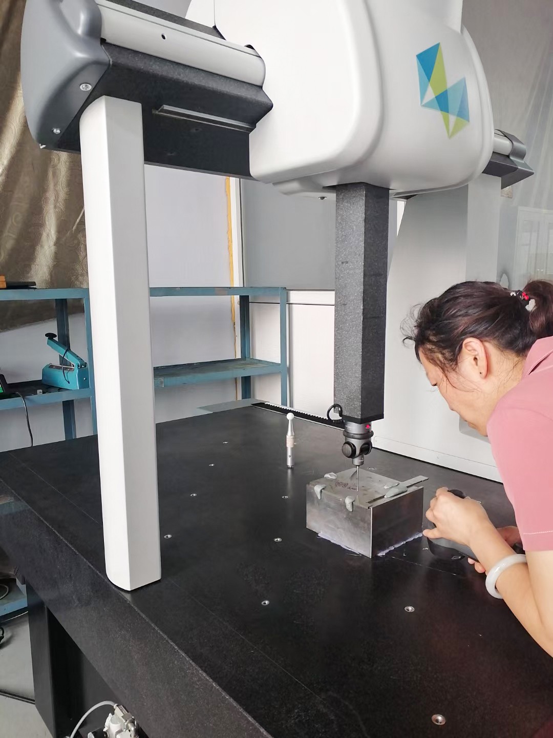
Coordinate Measuring Machine (CMM), also known as three-dimensional measuring instrument, serves as the precision inspector in precision manufacturing. It accurately detects geometric parameters including dimension, form and position tolerance of workpieces, and is widely applied in aerospace, automobile manufacturing, precision machinery and other industries.
Its micrometer-level measurement accuracy relies not only on inherent equipment performance, but also on standardized operation and full-process precision control. A tiny error of merely 0.003mm may lead to scrapped aerospace components and abnormal noise of automobile engines. This article elaborates core application principles of CMM from practical operation procedures to precision guarantee measures.
Preparations determine the reliability of measurement benchmarks, covering environment, equipment and workpieces.
Environmental Adjustment
Maintain ambient temperature at 20±2℃, and 20±0.5℃ for high-precision measurement; hourly temperature fluctuation shall not exceed 0.5℃ to avoid thermal expansion and contraction deformation.
Relative humidity keeps between 45% and 65% to prevent equipment corrosion and static interference.
Keep a distance of over 5 meters from vibration sources such as machine tools and compressors; avoid direct air conditioning airflow blowing onto the equipment.
Equipment Inspection
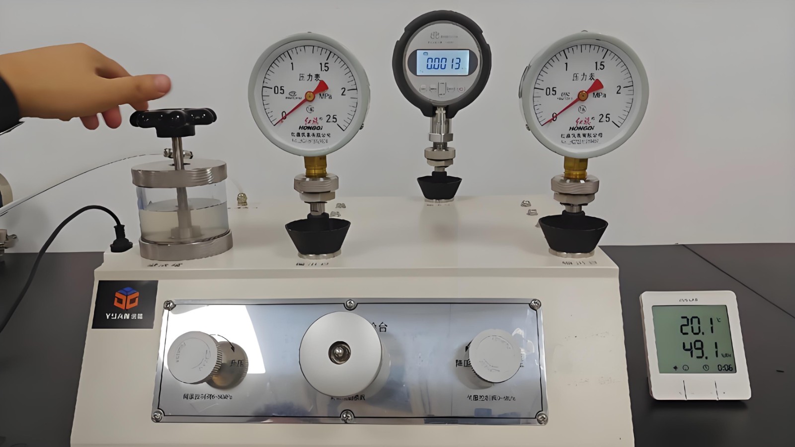
Stabilize air source pressure within 0.4-0.45MPa with total air pressure no less than 0.6MPa; drain oil-water mixture in the triple filter when liquid level exceeds 5mm.
Wipe guide rails with anhydrous alcohol; clean grating scales with acetone instead of alcohol to remove dust and metal chips.
Preheat the equipment for more than 30 minutes. Power on in sequence: control cabinet, computer, measurement software and servo system, then complete three-axis homing.
Workpiece Preprocessing
Remove surface oil stains, burrs and fingerprints with anhydrous alcohol; eliminate residual machining stress of thin-walled parts.
Keep workpieces thermally balanced with measurement environment: 4 hours for small parts and 8 to 24 hours for large parts.
Fix workpieces with flexible fixtures or plasticine with clamping force no more than 5N; evenly support large workpieces to prevent distortion.
Probe Configuration and CalibrationSelect contact or scanning probes and preferred ruby stylus according to workpiece features; take rigidity influence of extension rods into consideration. Calibrate stylus length and radius using standard balls with tolerance of ±0.5μm. Recalibration is mandatory after stylus or angle replacement, with calibration error controlled within 1μm.
Coordinate System Establishment via 3-2-1 MethodDefine Z-axis with no less than 3 measuring points on the reference plane, X-axis with minimum 2 points on the reference line, and origin via reference points. Align workpiece coordinate system with machine coordinate system to reduce conversion error.
Measurement Path Planning and ExecutionSet measuring point distribution via manual pre-measurement: over 5 points for circles and interval of one-tenth curvature radius for curved surfaces. Compile automatic programs for batch measurement.Adjust moving speed between 10-50mm/s and slow down to below 5mm/s when approaching workpieces to prevent collision. Conduct dry run to check path interference before formal automatic measurement.
Data Processing and Report GenerationThe software automatically calculates geometric parameters such as distance, roundness and parallelism, and judges product qualification by comparing measured values with drawing tolerances. Export reports containing actual readings, tolerance range, out-of-tolerance marks, operator information and ambient temperature.
Park the probe at safe standby position, clean workbench and guide rails, and release residual pressure before cutting off air supply.Save measurement programs and data, generate inspection reports and record operation logs including measuring times, error conditions and abnormal faults.Seal and store styluses and standard balls for rust prevention during long-term idle period.
Adopt 300mm-thick concrete base and air spring vibration isolators to limit amplitude within 1μm.Compressed air shall meet ISO8573-1:2010 Class 4 cleanliness standard with pressure fluctuation within ±0.01bar.Equip independent grounding with resistance lower than 4Ω, apply shielded cables and keep away from frequency converters and transformers to avoid electromagnetic disturbance.
Conduct annual calibration of guide rail straightness and perpendicularity with laser interferometer complying with ISO 10360 standard.Clean styluses weekly and calibrate non-contact laser scanners quarterly; maintain stable trigger force at 0.1-0.5N.Lubricate guide rails with special oil every week and control axial lead screw backlash within 1μm.
Operators shall be proficient in handheld controller functions; never place head beneath Z-axis.Verify repeatability with standard parts: repetitive measurement error ≤1μm for 10 tests and reproducibility error ≤2μm among different operators.Troubleshoot surface scratches, loose stylus and unstable air pressure when data fluctuation exceeds 3σ range.
Adopt proper fitting algorithms such as least square method for circular fitting and avoid overfitting.Activate error compensation model to calibrate 21 geometric errors, limiting volumetric error within 5μm per meter.Update software firmware regularly and close irrelevant programs to guarantee stable data collection.
Aerospace Industry: Measure contour of engine blades with tolerance of ±0.002mm via standardized operation and environmental control to guarantee mass qualified inspection.
Automotive Manufacturing: Detect radial runout of transmission gear rings through automatic programs and repeated calibration to ensure assembly precision.
Precision Electronics: Inspect semiconductor components under 20±0.5℃ constant temperature with non-contact probes to avoid surface damage.

Copyright © 2025 Qingdao Zhengrong Precision Machinery Co.,Ltd. All Rights Reserved Powered By HiCheng

